
Quad 57 - Meinholf's Rebuild
"The following story is from a client in Germany (Meinolf) that had some Quad 57 ESL speakers that needed repair. Meinolf has been kind enough to provide a translated account of the repair process.
Meinolf was also patient enough to wait for the repair kit we sent for around a month while it travelled around the globe due to
mis-direction from Australia Post, even though the shipping labels were clearly marked with the correct address.
Meinolf has not just repaired the speakers and reported the subjective results, he has also taken frequency response measurements of before and after the repair - this is worth looking at below." Rob
Quad ESL Refurbishment – Part 1 |
|
| Preparing work – disassambling „Refurbishing an elektrostatic loudspeaker working with 6000V? You are crazy!“ How did my story start? Looking for a second pair of ESL57 I found a defect pair in my town for low price via ebay. Serial number and optical appearance seemed well and I risked it. HiFi friends, reading the quad esl refurbishing book of Sheldon Stokes , and studying a very interesting homepage in australia encouraged me. 500 australian dollar – they were mine! The first quad had a defect powerswitch, the other a defect fuse. Thats all – first viewing. Listening to the quick repaired pair they sounded ill. Treble finished at 4kHz, they were buzzing and the bass panel seems not to exist. |
|
Superior Finished Speaker |
”Hour of truth” we say in Germany, the speaker has to be refurbished completly!! 1. Disassembling front grillThe grill is produced by thin pressed aluminium and has to be handled carefully. After dismantling the side wood (2 or 3 wood screws), the clamps must be removed. I used a thin screwdriver. At the end the bottom screws had to be removed. The top of the grill is not fixed by screws but held by a small gap in the top wood frame. Opening and removing is like opening a boot lid...... |
2. Disassembling back grillThe grill is produced by thin pressed aluminium and has to be handled carefully.
|
|
3. Disassembling bass panelKnowing, that my bass panel will be refurbished completly I cutted the electric connection and did not use a solder.Removing the panel needed removing 2 aluminium brackets mounted between the two bass panels on the front side. After removing this brackets the panels, which are a little bit arced and tensioned, can be moved to the midst. Finished! |
|
4. Disassembling treble panelIt's similar, you only have to decide whether cutting the wires or soldering. If you decide to unsolder you first of all have to remove the audio uni |
|
5. Disassembling EHT UnitLooking from the back the EHT Unit is on the right side. It's fixed by 4x M5 screws. Loosing the last screw be careful: if the unit crashes in the dust-cover of a panel, you have to restore it. Unsoldering three wires (Bias bass panel, Bias treble panel, ground) the unit is removable. |
|
6. Disassembling Audio UnitThe audio unit ist the big and heavy (!!) block on the left side. It is held by M6 screws. After loosening screws you can turn the unit round and unsolder the wires. Don't forget to mark the wires!! If you forget, a schematic in Sheldon Stokes book help to reassemble well. |
|
7. Disassembling Dust cover framesAfter removing the complete panel, the dust cover frames must be removed too. They are build of ultralight wood frames, which covered by a very thin heat-shrinking film. The film is sensitive and may be damaged easily. Be careful. Using a sharp knife or scalpel the panel unit is opened. |
|
8. Disassembling the stator unitNow the strong work starts. The panel is build by two stators (plastic material sensitive to high temperature like a soldering). Both part are fixed by 64 (!!!) rivets. The rivets must be removed. Awfull!! I tried different ways. The best one was to use a box column drill and a 3.5 mm metal drill with cutting oil. With fingertip feeling and correct pressure rivet by rivet can be loose on the smaller side. Then you move the loose rivet through its own hole and remove it from backside. Your first trial should be on the outside perimeter. If you damage a little bit it doesn't matter. The inside rivets must be removed very carefully. It's the later refurbished EHT rail!! Important: mark on both sides and don't drill the rivets which are used for connecting the EHT BIAS!!! Wow, first part has been done, second part follow! |
|
|
Note from Rob, E R Audio. The rivets can also be removed by squeezing the head of the rivet with pliers first one way than at 90 degrees to form a crushed square, this will pass through the original hole. |
|
Quad ESL Refurbishment Part 2 |
|
Preparing work after disassamblingFollowing the parts are listed laying on my table: - 2 frames (wood and ressed wood) carrying the hole qua- 6 damaged and uggly dustframes - 4 stators for the treble unit with burned holesand areas - 8 bass panel stators in good condition - 2 EHT units with old wachs packed boards - 2 audiounits with old bananajacks and without shorteningfus- 4 distance rubber buffers mounted on bass panel dust fra- 2 damaged front grills - 2 back units |
|
1. Dust Cover FramesThe frames build of light wood. Specially the edges must be carefully used. Left picure shows the arced frame and a grey colored film, which is destroyed nearby the outer edge. After removing the old (thick!!) film the wood surface must be cleaned and prepared for new mounting of heat-shrink film (much thinner than original). I used a Dremel and a pad sander to remove old adhesive surface. |
|
2. Treble Panel StatorsFirst of all a picture shows the effect of an old audio unit without safeshortening gasdiode. Using wrong amplifier or too much power (>25 Watt) and the conductive film shortens and it's like a thunderstorm. The bias and high voltage burns a hole in the mylar film and the plastic stator. It's a deep defect and the result is a lost of high frequency transfer!! The complete areas must be restored. First of all I sanded the area and measured with a standard voltmeter the border to conductive area. Using a special silver color (repairing car glass heating a tricky tip!!) and closing with an isolating color the area is conductive again. |
|
|
The perimeter must be cleaned carefully to restore a clean and rough surface for using the special glue later on. 3. Bass statorsThey are in good condition and the film has to be removed only. The perimeter must be cleaned by using a dremel. |
|
4. EHT UnitThe EHT is like a bottleneck. Using the EHT without refurbishing it makes no sense. The voltage specially for bass panels will be too low, because the diodes underly an aging process. They must be exchanged. Many reasons resulted in planning a complete new EHT board. The diodes are changed by serial 1N4007 Diodes (2 for 1 old diode). The EHT Bias runs through a 20MOhms resistor (treble) followed by a NE2 lamp with parallel capacitor (10nF /1000V). The NE2 lamp indicates health of later mounted mylar or hostphan film. If it blinks every 2-4 seconds, the film is healthy. If glimming (flashing) continuously you have a shortcut or leakage current. I think it's a very helpful tool and it solves the often existing rest-buzzin The left picture shows the old unit, a picture of the new EHT Unit with Neon lamp follows later. The bulgin jacket was in good condition and seems vintage like, so I didn't change it. |
|
5. Restoring audio unitTo restore and improve the audio unit two steps necessary: - changing banana jackets and - implantation of a high voltage gas discharging diode. Why? The banana plugins are originally made of plastic and I think it's the only cheap original part used and must strongly be changed. The high voltage gas discharging diode will prevent the effect of too much power and shortcutting treble panel. To prevent (protect) the treble panel two ideas exist and are written in Sheldons book: - a construction of z-diodes - using a highvoltage gasdischarging diode The last one seems to better but it was difficult to find it! Thanks to ebay: I found 4 pieces in USA, sold them and received 20 pieces. What a service!! Based on Sheldons book and supported by Ralph Stens (http://www.rstaudio.de) I soldered the diode and felt safe now!! The change of banana plugins is a must do!! Often they are broken or in bad condition. The picture tell the story of change. If necessary isolate the new loudspeaker plugin with a heat-shrinking on the negative pole. The wires MUST be soldered / unsoldered, they are very short! To clean the surface of audio unit I used orange oil. It cleans rests of wax perfectly and the surface take a nice vintage impression. Nothing forgotten the third part follows. |
|
Quad ESL Refurbishment Part 3 |
|
|
Diaphragm replacement, dust cover replacement, new wire ...here we are, everything is well prepared. First of all I had to be patience until the parcel arrived Germany and passed custom service. The parcels journey round the globe starting 22.6.2016: Perth AUS --> Paris FR --> Sydney AUS --> Bisbayne AUS --> Perth AUS --> F'furt --> Delivery................ 19.07.2016: the parcel arrived German custom!! (Australia Post makes mistakes more often that we would like!! - Rob, E R Audio) Personal quotation emailing with Rob: Hi Rob, everything is fine!! Your parcel was undamaged and unopened. The custom service was asthonished about contents and asked me three times if their Greetings and very best regards Meinolf |
|
List of tools I used: big table (min. 140 x 100 cm) |
|
 |
 |
 |
 |
|
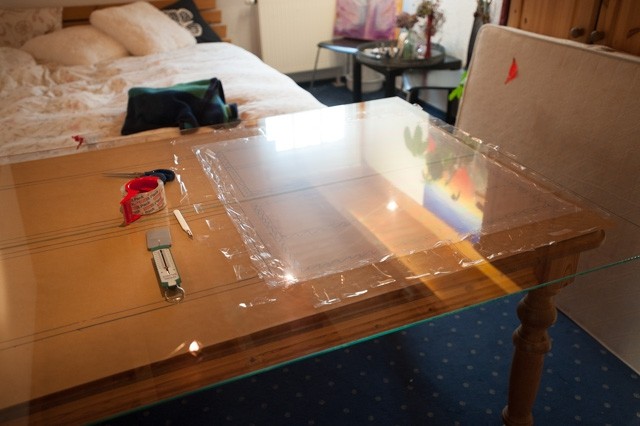
Perfect packing and not damage the parcel arrived in Germany after a journey two times round the globe unbelievable!! Preparing: Very important is an absolute plane and clean working surface!! I bought two glass plates (normal use for building aquarium or terrarium) covering the complete table. They have a hardened surface and resist scratches. |
|
 |
 |
|
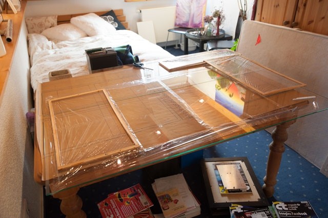
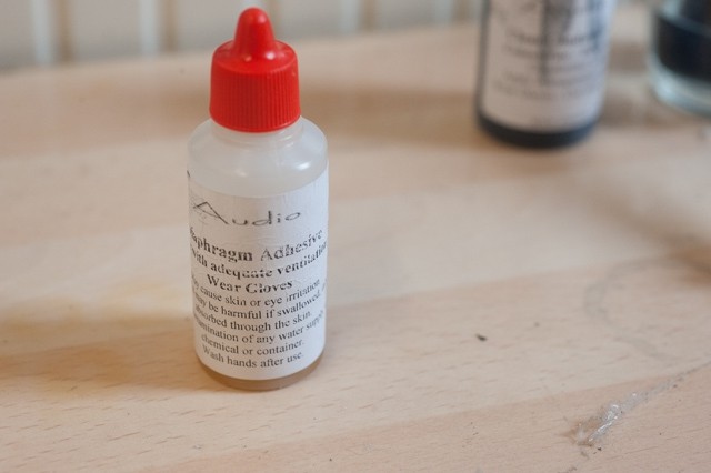
Under the glass plate I arranged packing paper and marked it with the circumferences of the pairs of different stators. This is helpful not to paint on glass or film later. Restoring the stators with mylar-c / hostaphan: Using the tensioning tool (very helpful and exact working!!) and in a special sequence (both are secrets of Rob I will not tell them here) the diaphragm is tensioned. This is the secret of later success. You have to work absolutely concentrate and careful. Don't make a mistake and be patient. The stators are glued with a special diaphragma-adhesive. It is important to use it continuously and INSIDE the rivet holes. After preparing the glue film the stator 1st place on the tensioned diaphragm by orientating on the marked areas of packing paper. It's necessary to press the whole circumference and to weight down the complete stator. I used a piece of wood and put a staple of magazines (if unreaded: it takes 15 hours time ;-) ) The glueing process need time depending on temperature and humidity. Don't stop the process too early!! |
|
 |
 |
|
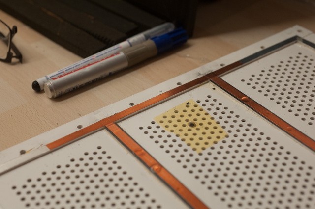
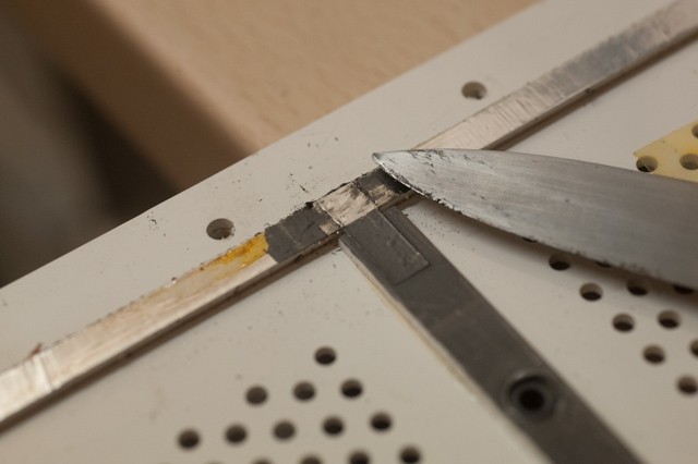
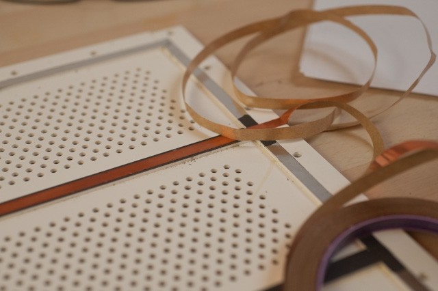
Next day you (carefully - Rob) cut the pair wise prepared stators with a sharp scalpel out of overlapping diaphragm. (you can also use a hot soldering iron to cut the panel free from the film, this will fuse the cut edge of the film so tears will not occur - Rob). The surface has to look like a calm and silent sea. The process has to be done three times: 1 pair of treble panels and 2 pairs of bass panels using different diaphragm and different tensioning. Refurbishing EHT Unit : A point deciding good sound or not, buzzing or not, distortion or not, is refurbishing the EHT unit. And also important is a first class input of BIAS wires to air-gap-spacers. The bass panels have a perimeter too, which should be rebuild too. Refurbishing the old aluminium foil an very thin copper foil is used and glue (self adhesive) over the aluminium. I preferred to measure the complete process with a digital multi-meter. |
|
 |
 |
 |
|
|
Coating of diaphragm : After cleaning the fresh mounted diaphragm (Hoover) the surface is coated with a special coating fluid developed by E R Audio. The sponge is perfect trimmed, the height of ml is exactly used as Rob described in his manual. You need very good light the fluid is transparent!!! Be sure not to coat the outer area. You risk leakage bias later on. |
|
 |
 |
|
Again 4 hours patience is needed. If you have measure the coating area with a high ohm voltmeter. Mounting of stators: First of all you have make holes for using the plastic screws through the air-gap-spacers and copper foil on the other side. To perforate the diaphragm the best way is using a solder with LOW temperature (150 - 200 degrees C). So you are able to control it. |
|
 |
 |
|
After cleaning the copperfoil with alcohol the stators are combined by plastic screws. For input BIAS I used M3 screws and special washers. Again: test electric connectivity!! Dustcover : A simple method shows good results. The wood frames are glued with a double sided adhesive Tesafilm. The heat-shrinking foil must not be tensioned, you only have to press the frame on the foil. Carefully use with enough distance of a heat-gun produces perfect tensioned dust covers. |
|
 |
|
Now all components are ready for the last step. Part 4 |
|
|
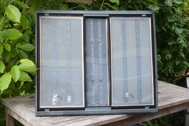
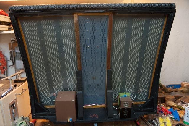
The last part describes definive reassembling and results In front of my working desk 3 panel wait for assembling. First of all the treble-panel is positioned in the middele of the big frame. 2 small pins fix position. (perhaps you have to look for them) Later on the treble panel is fixed by the to bass panels in front of the treble panel. The upper part of the panel is free and can tensioned elasticly. Following the bass panel is move to the left side behind the aluminium angles. Last millimeters need pressing the outer frame area from behind, so that the bass panel is little bit arced (curved - Rob). The same procedure with the bass banel on the right side. I positioned all panels with a small air gap round (2-4mm). And the treble panel should stand central and the foil has to be free and not covered by the wood frame. |
|
 |
 |
 |
 |
|
Finishing the position is done by remounting the aluminium brackets at top and bottom with the original wood screws. Next step is backside refurbishing. Both bass panel receive a luster bracket mounted an the bottom of big frame. Wire connection is so done easily without soldering. Next step is remounting the EHT Unit. 4x M5 Screws fix the Unit underwards. (from underneath - Rob) My developed new EHT Unit uses special terminals, you only have to click wire, which has prepared with wire-end-..... The rest of wires of the treble panel are soldered in the head positioned Audio-Unit. Last step is the rest of the wiring, fixing the audio unit with 4 M6 screws and controlling all wire are correctly mounted. |
|
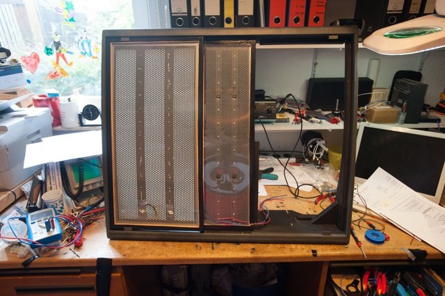
Without front grille you see the result. |
|
|
|
and here, the back with EHT and Audio unit |
|
|
|
Hour of truth:The quads are on wire - switch on a short silent crackle - calmness One hour patience, the panels need time to load. The neon lamps glim every 5-10 seconds, a good sign?? Then MUSIC: what an overwelming impression the quads are running famously Music is solved from speaker, great stage, quick sound, great great music!! Nothing remembers to the defect pair that stands in front of me. Astonished I sat hours and listened one vinyl, the next, CD, tape....... But now I want to know exactly and reproducible what has happened. Until Disassembling I made a measurement of the defect quads (in combination with a Ripol). |
|
 |
|
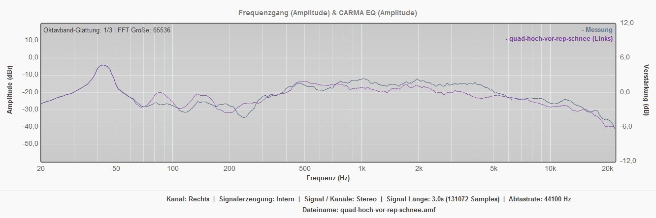
|
Above, the frequency response of the speakers before repair - note: A Ripole sub is being used hence the better than usual bass response. Reason: the defect by burning a hole with to much power and the absence of fusing the treble panel. After refurbishment a complete different result. Nearly linear the signal runs over quads. The differences between left an right channel a caused by different damping and below 200 Hz caused by a room-mode. |
|
 |
|
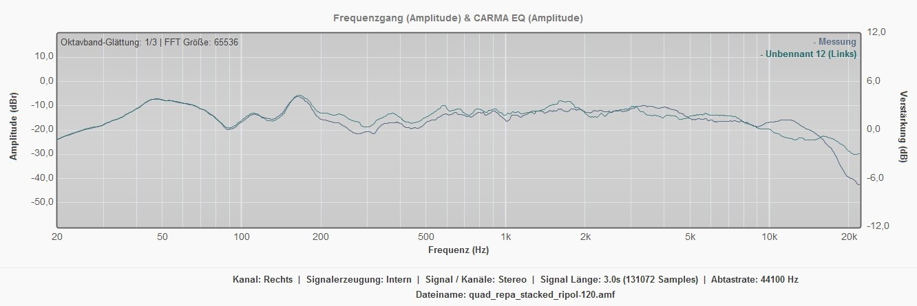
|
Above, the frequency response of the repaired speakers You see a deep loss of signal between 100 400 Hz and after 4kHz there was loss of many dB. Reason: the defect by burning a hole with to much power and the absence of fusing the treble panel. After refurbishment a complete different result. Nearly linear the signal runs over quads. The differences between left an right channel a caused by different damping and below 200 Hz caused by a room-mode.
The measurement shows impressive the result of refurbishing the old quads. They are now better than original (Rob M.) Quintessenz: If spend a lot of time (40 60 hours), use correct tools and invest 150 you listen to a quad ESL 57 that is better than original. I am listening music as never before! Many thanks Ralph Stens, who encouraged me complete time and to Rob Mackinlay. He supported me by mail everywhere and anytime. Thank you so much, Rob!! Reference: The Quad ESL - Home Electrostatic Loudspeakers By ER Audio RStAudio.de DIY Audio Homepage Audio Haven | Quad Stewart Penketh Element Repair Page DuPont Teijin Films Europe - Home - DuPont Teijin Films Quad ESL Serial Numbers |
|
Many thanks to Meinolf for the description of the journey taken to repair his Quad 57’s. I know the translation from German to English has taken some time and effort on his behalf and we are grateful for that.I have tried not to make any changes to the original text sent by Meinolf, just some minor spelling corrections here and there where the meaning may have been misunderstood.Rob - E R Audio Pty Ltd |
|